The concept of solids of revolution — shapes formed by rotating a two-dimensional curve around an axis — is a fundamental topic in mathematics, often explored in calculus and geometry. If you’ve ever sat through a math class learning about solids of revolution you might have wondered, “When am I ever going to use this?“.
However, beyond the theoretical, this concept has practical applications in the world of design and manufacturing. Imagine turning a simple mathematical curve into a tangible object like a vase or bowl. This is where the power of computational tools and programming comes into play.
FreeCAD is an open-source parametric modeling software which offers a versatile platform for translating mathematical ideas into digital models. When paired with Python, FreeCAD allows you to script and automate the creation of complex geometries with mathematical precision.
In this article, we’ll explore how Python can be used to interact with FreeCAD to model solids of revolution. By the end, you’ll see how a simple mathematical function can be transformed into an elegant 3D design, ready for visualization, simulation, or even 3D printing.
Setting up the environment
First things first, download and install FreeCAD: Head over to https://www.freecad.org/downloads.php and grab the version that matches your operating system.
Once installed, you have two main ways to interact with it:
- FreeCAD GUI (Graphical User Interface): This is the standard way most people use FreeCAD. You can create and modify models manually, but it also has an integrated Python console.
- FreeCAD CLI (Command Line Interface): If you prefer working in a terminal or want to automate tasks without opening the full FreeCAD application, the CLI is your friend. It supports interactive Python scripting, letting you create and manipulate models entirely from the command line.
The script in this article works in both environments.
Start FreeCAD (GUI) and make sure you have the Python Console visible: View > Panels > Python console
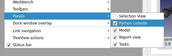
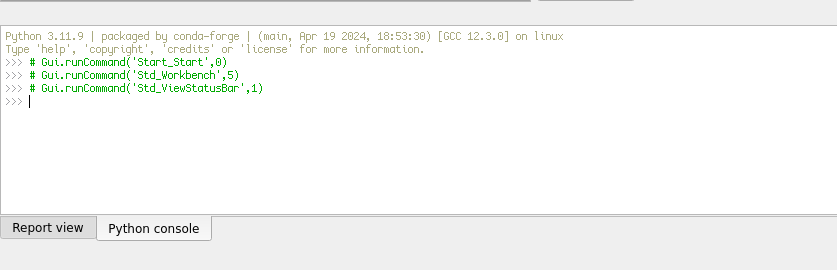
You should be able to see a Python console like this:
Creating a Bowl
Creating a bowl in FreeCAD is easier than you might think — all it takes is a simple curve and a bit of Python. Instead of using a perfect quarter-circle, we’ll approximate the smooth curve by connecting a series of points to form a wire. In this example, I’ll use 20 sections (21 points) to define each profile: one for the inner curve of the bowl and one for the outer edge, totaling 42 points. You can adjust the number of points depending on your computer’s performance and the level of detail you’re after. Once the profiles are set, we’ll revolve them around an axis to create a smooth, symmetrical bowl shape. This approach gives you more control over the design and helps you understand how complex shapes can be built from simple elements.
A quarter-circle is defined by the equation (where is the radius):
However, if we want to divide the quarter-circle into points that are equally spaced along its arc, it is more appropriate to use a function based on the angle in the circle. By defining the function…
…we can calculate the angle for each section as follows…
…where is the total number of sections and is the current section index (ranging from to ).
Using this approach ensures that the points are evenly spaced along the arc rather than along the x-axis. We can then multiply each coordinate by to scale the points to the correct radius.
I will call this function create_circle_q. The spacing for variable assignment in the code below is simply for readability and is not necessary for functionality.
import FreeCAD as App
import Part
import Draft
import math
def create_circle_q(r: float, n: int):
for i in range(n + 1):
a = (math.pi / 2) * (i / n)
x = math.cos(a)
y = math.sin(a)
yield App.Vector(r * x, r * y, 0)
def create_profile():
# Define the outer and inner quarter-circle profile
outer_points = list(create_circle_q(10, 20)) # A quarter of a circle with a radius of 10 defined by 20 points
inner_points = list(create_circle_q(8, 20)) # A quarter of a circle with a radius of 8 defined by 20 points
# Connect the outer and inner (reversed) profiles to form a closed loop
return outer_points + inner_points[::-1] + [outer_points[0]]
# Create a new document
doc = App.newDocument("RevolutionSolid")
# Create a profile
profile = create_profile()
# Create a closed wire from the points
wire = Draft.makeWire(profile, closed=True)
# Create a body
body = doc.addObject('PartDesign::Body','Body')
# Move wire into body
wire.adjustRelativeLinks(body)
body.ViewObject.dropObject(wire, None, '', [])
# Perform revolution of solid (aroud base x axis)
revolution = body.newObject('PartDesign::Revolution','Revolution')
revolution.Profile = (wire, ['',])
revolution.ReferenceAxis = (doc.getObject('X_Axis'), [''])
revolution.Angle = 360.0
# Hide wire once used
wire.Visibility = False
# Add the solid to the document
doc.recompute()
print("Solid of revolution created.")
# Export to STL file
output_filename = "/tmp/solid.stl"
Part.export([revolution], output_filename)
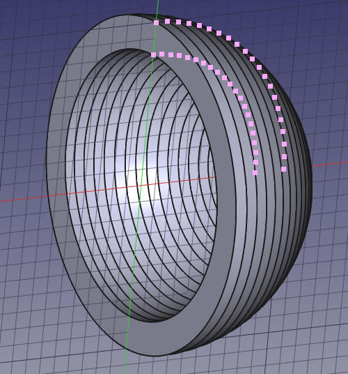
print(f"Exported optimized cup to {output_filename}")This is what the resulting solid looks like:
Creating a Torus
To create a torus, we need to generate a circular profile that can be rotated around an axis. This is achieved by defining a function that calculates points along a circle with an offset from the origin. These points will form the cross-section of the torus.
The function create_circle_with_offset generates a set of evenly spaced points along a circle of radius r, using trigonometric functions (cos and sin) to determine the coordinates. The circle is then offset by a given (offset_x, offset_y) to position it correctly in space.
The create_profile function uses create_circle_with_offset to generate two circles (an outer and an inner profile) which define the thickness of the torus. The points are then combined into a closed loop by reversing the inner profile and ensuring continuity. This closed profile can then be revolved around an axis to form the 3D torus.
# The function creates points of a circle with an offset
def create_circle_with_offset(r: float, n: int, offset_x: float, offset_y: float):
	for i in range(n + 1):
		a = 2 * math.pi * (i / n)
		x = math.cos(a)
		y = math.sin(a)
		yield App.Vector(offset_x + r * x, offset_y + r * y, 0)

def create_profile():
	# Define the outer and inner profile
	outer_points = list(create_circle_with_offset(10, 80, 0, 15))  # A circle with the radius 10 with the offset (0, 15)
	inner_points = list(create_circle_with_offset(8, 80, 0, 15))   # A circle with the radius 8 with the offset (0, 15)

	# Connect the outer and inner (reversed) profiles to form a closed loop
	return outer_points + inner_points[::-1] + [outer_points[0]]
Integrating The New Functions to Create a Torus
By replacing the original point-generation function with create_circle_with_offsetand updating the function call, we can now generate the correct profile for a torus. Below is the updated code, where the new functions seamlessly define the circular cross-section and prepare it for revolution.
The final code for generating the torus is:
import FreeCAD as App
import Part
import Draft
import math
# -- changed part: start --
# The function creates points of a circle with an offset
def create_circle_with_offset(r: float, n: int, offset_x: float, offset_y: float):
for i in range(n + 1):
a = 2 * math.pi * (i / n)
x = math.cos(a)
y = math.sin(a)
yield App.Vector(offset_x + r * x, offset_y + r * y, 0)
def create_profile():
# Define the outer and inner profile
outer_points = list(create_circle_with_offset(10, 80, 0, 15)) # A circle with the radius 10 with the offset (0, 15)
inner_points = list(create_circle_with_offset(8, 80, 0, 15)) # A circle with the radius 8 with the offset (0, 15)
# Connect the outer and inner (reversed) profiles to form a closed loop
return outer_points + inner_points[::-1] + [outer_points[0]]
# -- changed part: end --
# Create a new document
doc = App.newDocument("RevolutionSolid")
# Create a profile
profile = create_profile()
# Create a closed wire from the points
wire = Draft.makeWire(profile, closed=True)
# Create a body
body = doc.addObject('PartDesign::Body','Body')
# Move wire into body
wire.adjustRelativeLinks(body)
body.ViewObject.dropObject(wire, None, '', [])
# Perform revolution of solid (aroud base x axis)
revolution = body.newObject('PartDesign::Revolution','Revolution')
revolution.Profile = (wire, ['',])
revolution.ReferenceAxis = (doc.getObject('X_Axis'), [''])
revolution.Angle = 360.0
# Hide wire once used
wire.Visibility = False
# Add the solid to the document
doc.recompute()
print("Solid of revolution created.")
# Export to STL file
output_filename = "/tmp/solid.stl"
Part.export([revolution], output_filename)
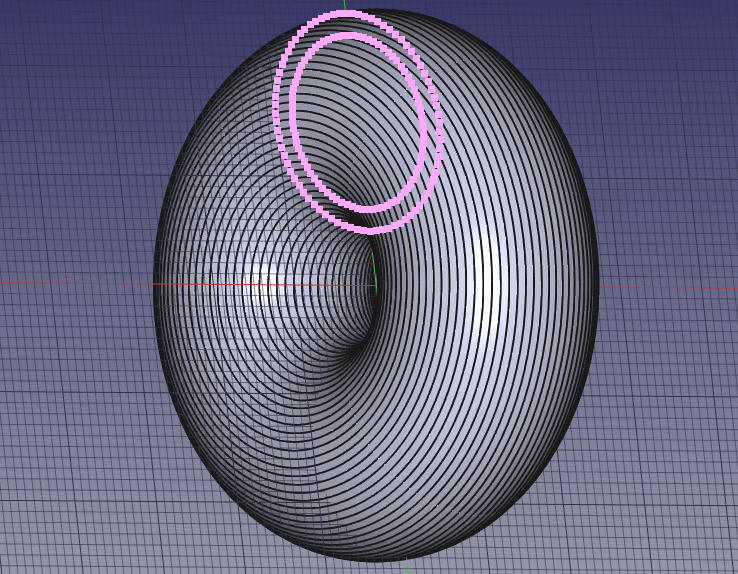
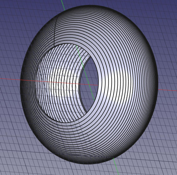
print(f"Exported optimized cup to {output_filename}")This is what the resulting solid looks like:
Expanding Possibilities With Mathematical Functions
By modifying just these two functions, we open up almost endless possibilities for creating profiles for solid revolution. The limit is our imagination when choosing which mathematical functions to use!
In the following sections, we explore other mathematical functions that can define profile shapes, allowing us to generate a variety of 3D solids through revolution.
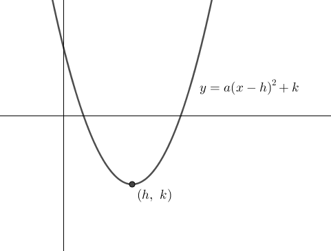
Parabola (Parabolic Dish Profile) → Paraboloid (Satellite Dish, Reflector)
Solid Revolution
- If you revolve a parabola or arch around the y-axis, you create a paraboloid (a 3D bowl shape) or other shapes.
- This shape is used in satellite dishes, reflectors, and telescope mirrors.
Application
- Math link: Quadratic functions & conic sections
- Real-world use: Satellite dishes, reflector telescopes, rolers etc.
A Parabola Follows a Quadratic Equation
where is the vertex. We will also restrict the function using a width () such as
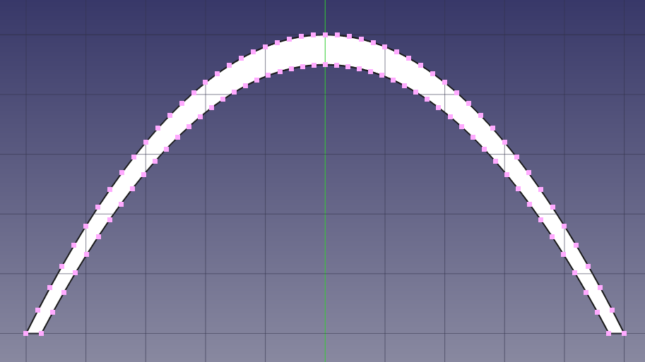
Implementation
def create_parabola(a: float, h: float, k: float, n: int, w: float):
	for i in range(n + 1):
		x = -w/2 + (w * i / n)
		y = a * (x - h)**2 + k
		yield App.Vector(x, y, 0)

def create_profile():
	# Define the outer and inner profile
	outer_points = list(create_parabola(-0.2, 0, 10, 50, 10))
	inner_points = list(create_parabola(-0.2, 0, 9.5, 50, math.sqrt(4.5/0.2)*2))

	# Connect the outer and inner (reversed) profiles to form a closed loop
	return outer_points + inner_points[::-1] + [outer_points[0]]
This will create a hollowed out roller where the two parabolas, making up the profile of the arch, are connected at .
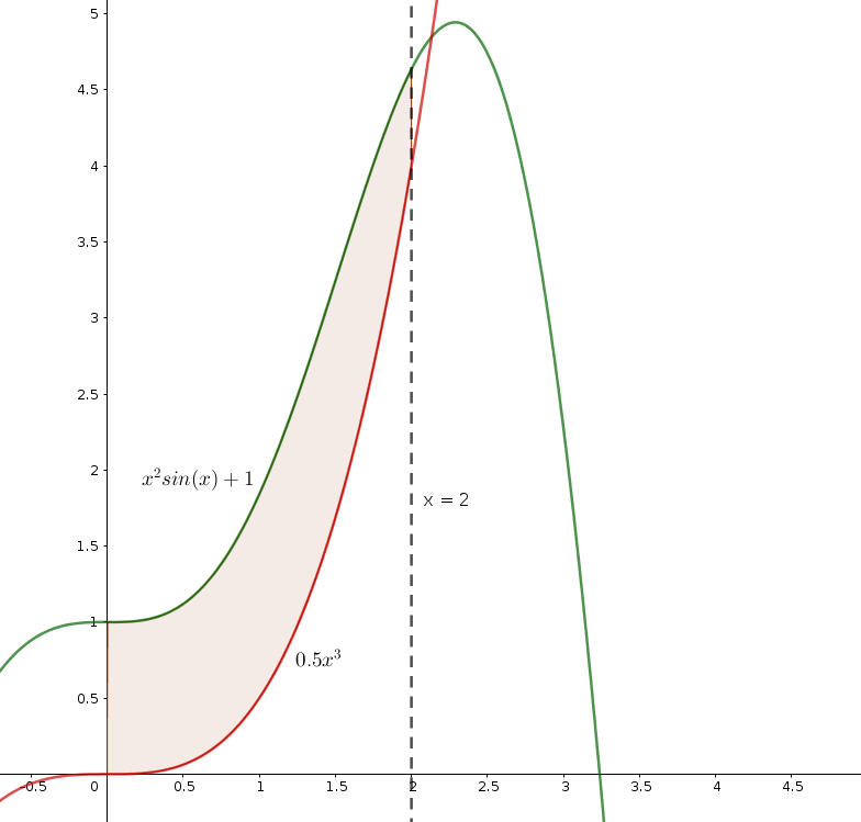
Using Two Different Functions to Define The Profile
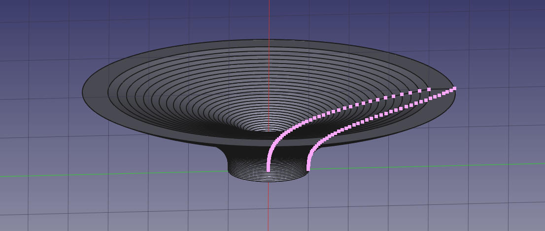
Now, lets create a profile using two different functions. I’ll use and in this example. I want to revolve the integral:
Hopefully this will result in a stylish bowl.
def create_curve(func, n: int, a: float, b: float):
	for i in range(n + 1):
		x = a + (b * i / n)
		y = func(x)
		yield App.Vector(x, y, 0)

def create_profile(n: int = 50, a: float = 0, b: float = 2):
	outer_func = lambda x: x**2 * math.sin(x) + 1   # x^2*sin(x) + 1
	inner_func = lambda x: 0.5 * x**3               # 0.5x^3

	# Define the outer and inner profile from a = 0 to b = 2
	outer_points = list(create_curve(outer_func, n, a, b))
	inner_points = list(create_curve(inner_func, n, a, b))

	# Connect the outer and inner (reversed) profiles to form a closed loop
	return outer_points + inner_points[::-1] + [outer_points[0]]
create_curve(func, n, a, b)
This function generates a series of points along a curve defined by a mathematical function.
- Parameters:
func: A mathematical function that takes anxvalue and returns a correspondingyvalue.n (int): The number of sections to divide the curve into (which results inn + 1points).a (float): The starting value ofx.b (float): The ending value ofx.
- How it Works:
- It iterates from
atob, dividing the interval intonsections. - For each
x, it calculates the correspondingyusing the provided function (func). - Each point is returned as an
App.Vector(x, y, 0), representing a 2D point in FreeCAD.
- It iterates from
The create_curve function works similarly to how numerical integration methods approximate the area under a curve, such as using Riemann sums. It divides the range from a to b into n small intervals and calculates the value of the function at each point within these intervals. This approximates the curve by generating discrete points instead of using an exact mathematical formula.
create_profile(n=50, a=0, b=2)
This function uses create_curve to build the outer and inner profiles of a bowl, then connects them into a closed loop that can be revolved into a 3D object.
-
How it Works:
- Outer Profile: Defined using the function y=x 2 s i n(x)+1 y=x^2sin(x)+1 y=x 2 s in(x)+1, which creates a wavy, dynamic outer curve.
- Inner Profile: Defined by y=0.5 x 3 y=0.5x^3 y=0.5 x 3, giving a smoother, more gradual slope to the inside of the bowl.
-
Steps:
- Generate the outer points by passing the
outer_functocreate_curve. - Generate the inner points with the
inner_funcin the same way. - To create a closed loop:
- Connect the outer points to the reversed inner points.
- Add the first outer point at the end to ensure the shape is fully enclosed.
- Generate the outer points by passing the
-
Output:
- Returns a list of
App.Vectorpoints representing the complete profile, ready to be revolved around an axis to create a 3D bowl.
- Returns a list of
This is what the resulting solid looks like:
Creating a Script That Can Automate The Whole Process in a Generalized Way
This approach can be easily generalized to create a wide variety of solids by simply reusing the create_solid_of_revolution function below with different mathematical functions for the outer and inner profiles. By defining the profiles with lambda functions or custom functions, you can generate a vast range of shapes, whether they are bowls, vases, or other revolved objects. The function is highly flexible and can be repeated indefinitely for various sets of functions, ranges, and resolution values.
import FreeCAD as App
import Part
import Draft
import math

# This function creates a curve based on a mathematical function from x=a to x=b
def create_curve(func, n: int, a: float, b: float):
	for i in range(n + 1):
		x = a + (b * i / n)
		y = func(x)
		yield App.Vector(x, y, 0)

# This function creates a profile based on curves from two functions from x=a to x=b
def create_profile(outer_func, inner_func, a: float, b: float, n: int):
	outer_points = list(create_curve(outer_func, n, a, b))
	inner_points = list(create_curve(inner_func, n, a, b))

	# Connect the outer and inner (reversed) profiles to form a closed loop
	return outer_points + inner_points[::-1] + [outer_points[0]]

def create_solid_of_revolution(doc, outer_func, inner_func, a: float, b: float, n: int = 50):
	# Create a profile
	profile = create_profile(outer_func, inner_func, a, b, n)

	# Create a closed wire from the points
	wire = Draft.makeWire(profile, closed=True)

	# Create a body
	body = doc.addObject('PartDesign::Body','Body')

	# Move wire into body
	wire.adjustRelativeLinks(body)
	body.ViewObject.dropObject(wire, None, '', [])

	# Perform revolution of solid (aroud base x axis)
	revolution = body.newObject('PartDesign::Revolution','Revolution')
	revolution.Profile = (wire, ['',])
	revolution.ReferenceAxis = (doc.getObject('X_Axis'), [''])
	revolution.Angle = 360.0

	# Hide wire once used
	wire.Visibility = False

	# Add the solid to the document
	doc.recompute()
	print("Solid of revolution created.")

	# Export to STL file
	output_filename = "/tmp/solid.stl"
	Part.export([revolution], output_filename)
	print(f"Exported optimized cup to {output_filename}")

# Create a new document
doc = App.newDocument("RevolutionSolid")

# Example call: (\int_{0}^{2}((x^2sin(x)+1)-0.5x^3 )~dx)
create_solid_of_revolution(doc, (lambda x: x**2 * math.sin(x) + 1), (lambda x: 0.5 * x**3), 0, 2, 50)